RAM Platform
What is Robotic Additive Manufacturing?
Additive manufacturing, commonly known as 3D printing, is a form of rapid prototyping in which digital files are turned into physical objects. This is usually done through laying down many successive thin layers of filament on a build surface to form a three-dimensional object.
Robotic additive manufacturing is an extension of classical additive manufacturing, commonly known as 3D printing. In robotic additive manufacturing a filament extruder is mounted to a robot arm. The freedom and flexibility of robot arms enables new and interesting ways of doing rapid and large-scale prototyping.
The TB-RAM CoE group has produced a user-friendly and accessible platform for doing robotic additive manufacturing. This page is an introduction to the TB-RAM platform and its features.
The roots
The RAM platform has its roots in the European Project Semester Project: 3D printing with Robotic Arm, which took place at Novia University of Applied Sciences 2017. Credits go to Job Trommelen, Juan Carlos García, Luc Richters and Poonam Khatti for their efforts in developing the prototype platform.
The EPS project produced the original extruder tool, which when attached to a robot would allow it to act as a 3D printer. A basic robot control program had been developed for translating limited G-Code (Command language for 3D printers and CNC machines) into robot movements.
The EPS Project extruder tool
Although this system worked for small demonstrations, it had a number of significant limitations which prevented it from bringing out the true potential of robotic additive manufacturing.
Due to the large size of the extruder tool, any form of freeform or non-planar printing would be nearly impossible. Attempting freeform or non-planar printing with this tool would likely have caused collisions between the build platform and build surface. A smaller and sharper tool design was required to enable freeform printing.
The original extruder tool used a binary signal for controlling extrusion. This limited the extruder to extruding the plastic at a single speed. This is opposed to conventional 3D printers which are capable of adjusting the extrusion speed on the fly, such as when printing bridging (overhanging) segments over long distances. Without the ability to adjust the printing speed, such overhangs would fail due to sagging.
Other considerations with the original design was the total weight of the tool. By keeping all the components of the extruder mounted on the tool itself, the robot would have to bear the weight of the entire assembly. This is sub-optimal due to the weight considerations regarding robot arms.
The new platform
With these limitations in mind, the TB-RAM CoE team set out to develop a new robotic additive manufacturing platform which solved each of these issues, while adding many new features to the entirety of the platform.
The new RAM platform is made up from several interconnected components which are specifically designed for robotic additive manufacturing. These include a number hardware and software components designed over the course of the project.
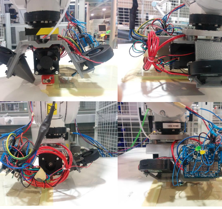
The extruder tool is the primary focus of a large part of the development. It has gone through many iterations, had failures, re-designs and improvements. The tool has come a long way since the start, and through the fantastic work of some of the CAD designers working in the project has reached a point where it was able to do both regular and freeform printing reliably, while also being easy to repair.
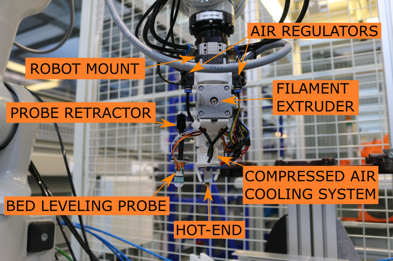
Notable features of the extruder tool is its purposefully pointed design all the way down to the nozzle. This design allows the extruder to tilt and rotate by a fairly large amount before risking collisions with the manufactured object. This change was facilitated by various design considerations which were taken at the start of the design process.
A new air cooling system was designed to allow for a compact cooling system, with the capability of providing significantly more cooling than the tool would likely ever need. Air flow through the system was optimized through computational fluid dynamic simulations to minimize noise while maximizing flow.
The touch probe
A significant hurdle in robotic additive manufacturing is the definition of a coordinate system which aligns the robot near-flawlessly with the build surface. This process used to take a significant amount of time with trial and error due to the small tolerances required when doing additive manufacturing. The robot being off by as much as a fraction of a millimeter could be the difference between a perfect and a failed print. Often it was impossible to get a perfect first layer due to the relatively warped shape of the build surface.
This problem was alleviated through the use of a touch probe mounted on the extruder tool. The touch probe allows for an automatic surface probing process to generate a highly accurate model of the build surface. This virtual representation can be used to fine tune the height of the robot movements over the adhering layer of the manufactured object. This process works flawlessly, even if the rough initial estimation of the build surface position is off by almost a centimeter.
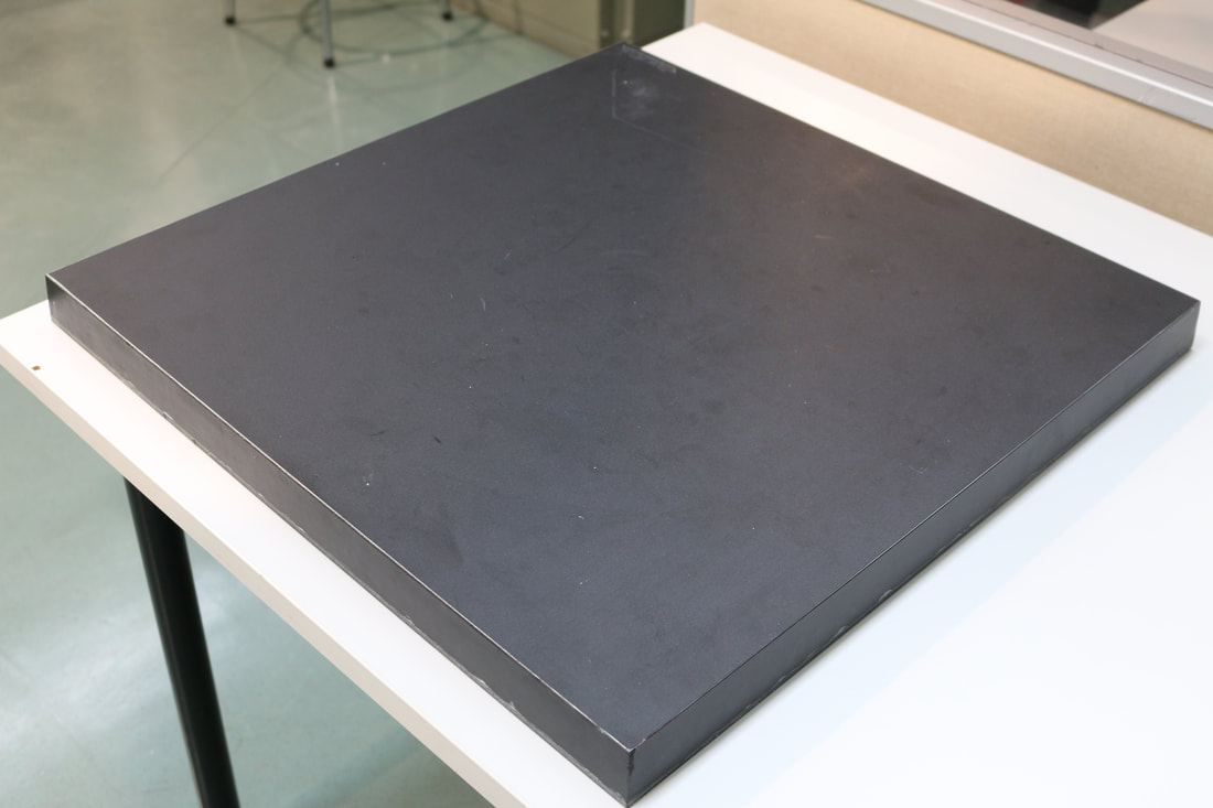
The build platform
Another component of the RAM platform which have gone through significant changes over the course of the project is the build platform, or print surface. This is the underlying build surface on which the manufactured object adheres to during the initial part of the printing process.
The first two iterations of the platform were unheated, but this proved to be an issue with larger prints due to the thermal warping effect of thermoplastics. The warping would cause larger prints to detach from the build surface. The final version of the build platform was assembled with a heating system which evenly distributes the heat across a large surface. This solution in conjunction with a <a href="https://www.3djake.com/info/guide/the-ingenious-buildtak-print-surface">BuildTak </a>top surface proved to be sufficient even for the largest prints.


The robot control program
The robot control program came a long way during the project. The robot control program is the piece of software which translates machine code produced by 3D slicing software into robot actions. The program manages a large number of tasks, from synchronizing plastic deposition with arm movements, to making sure the bed is level and that the heater is running.
3D slicing software such as Ultimaker Cura or PrusaSlicer produces a large number of different G-Code commands. Over time the robot control program had to incorporate the majority of commands relied on by 3D printer firmware. The robot control program became capable of running on the same type of machine code produced as conventional 3D printers, with very few modifications. This interoperability streamlined the design process for producing models with the RAM platform. Several conventional slicing programs have successfully been used together with the platform.
Freeform and non-planar printing
Freeform and non-planar printing was added to the RAM platform by extending the supported machine code of the robot control program with specialized freeform printing commands.
These commands are not used by conventional slicing software, so a custom parametric slicer was written in Javascript specifically for generating freeform prints for the robot. This slicer does not use pre-existing models, but instead generates the model based on mathemathical models.

Freeform slicer
Multiple freeform and non-planar objects have successfully been created using the TB-RAM platform. Freeform models have to be tested carefully in a digital-twin of the robot to ensure it can be safely printed without risking collisions with the table or the created object.

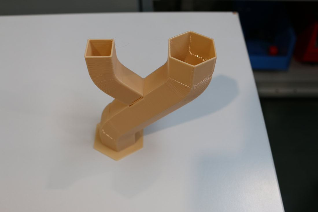
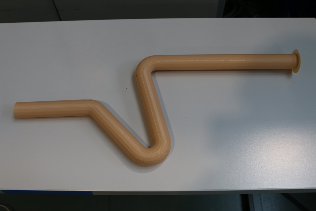
Freeform printing allows for several new ways of creating objects. Briefly summarized, freeform printing allows for three new ideas:
- Angled extrusions: Objects can be printed at varying angles, allowing the flat parts of extruded lines to face any direction. This kind of control could potentially be used to create objects which require high-precision rounded surfaces, such as airfoils.
- Non-planar printing: Layers with varying height can be printed to allow for natural curves. Using conventional 3D printing, the curves would be made from horizontal layers which would not match the curves. Using freeform printing the layers can actually be twisted together with curve itself, providing a much more natural and potentially stronger curved object. Further studies are needed over how non-planar printing affects object strength.
- Print-on-print: We proved that it is possible to attach new printed parts to existing printed objects, and in this way extend the object with new shapes. A study could be conducted in the optimal welding speed, temperature and distance. These factors affect the strength of the joining weld.
Name: Josefin Stolpe |
Name: Rayko Toshev |
Name: Dennis Bengs |
